 EN


What Wear Resistance Advantages Does Textile Ceramic Bring to Spinning Machines?
In a spinning line, a small yarn-contact part can become a large process problem when its groove wears. A guide that develops a ridge, a rough patch, or an enlarged contact path can change how yarn travels, raise the chance of abrasion, and make troubleshooting harder. That is why textile ceramic is commonly considered for yarn-contact locations such as guides, eyelets, tensioning paths, and related components.
From an application-engineering perspective, the useful question is not whether ceramic is automatically better than every alternative. It is whether a particular textile ceramic part has the material, geometry, surface condition, and mounting accuracy needed for a defined yarn and operating condition. This article explains the wear-resistance advantages in practical terms and shows what to verify before specifying a ceramic yarn guide or ceramic wire guide.
Why Wear at a Yarn Contact Point Matters
Yarn repeatedly passes over selected contact zones as it is spun, wound, twisted, or textured. Even where the load seems modest, long running time, yarn finish, airborne contamination, tension variation, and alignment error can gradually change a guide surface. A metal part may develop a groove or burr; a worn path may no longer support the intended yarn angle. The result can be inconsistent yarn travel rather than a single obvious failure.
A ceramic yarn guide addresses this problem by placing a hard, wear-resistant surface at the contact point. In many textile applications, the goal is not simply to make the guide last longer. It is to keep the yarn path more stable between inspections, provided that the grade, finish, and shape are appropriate for the process.
How Textile Ceramic Resists Wear
Hardness helps the guide retain its contact geometry
Many engineering ceramics used for textile components are selected because they resist abrasive contact better than conventional soft metals. When the guide surface resists gradual removal of material, the radius and profile of an eyelet or groove can remain closer to the intended drawing for longer. That can matter where yarn tension and travel angle depend on a controlled contact path.
However, hardness alone is not a complete specification. A ceramic eyelet can still be unsuitable if the bore size, entrance radius, polish, or installation position does not match the yarn route. More accurately, wear resistance has value when it protects a correctly designed geometry.
A smooth finished surface can reduce damaging contact
Precision grinding and polishing are relevant because yarn responds to the condition of the surface it touches. A smooth, well-finished ceramic surface can reduce opportunities for snagging compared with a damaged or poorly finished path. It can also make cleaning and visual inspection more straightforward. This does not mean every polished part will behave identically: fibre type, finish chemistry, speed, tension, and debris all affect the result.
For this reason, a ceramic wire guide should be evaluated as a finished component rather than only as a material label. Ask for the applicable drawing, critical dimensions, guide radius, surface-finish requirement, and inspection method.
Wear resistance can support repeatable maintenance planning
When a guide profile changes slowly, teams may have a more stable interval for visual checks and replacement planning. That is different from promising a fixed service life. Actual replacement timing must be determined by the machine, yarn, contamination level, and acceptance standard. Still, a wear-resistant textile ceramic component can help make the wear mechanism easier to monitor because the surface is intended to preserve its form under repeated contact.
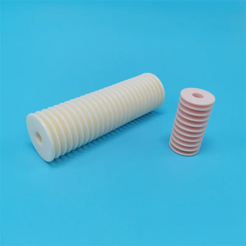 A smooth ceramic guide surface is specified together with the yarn route, guide geometry, and operating conditions.
Where the Advantage Appears on a Spinning Machine
Ceramic yarn-contact parts are used across fibre-production and textile machinery. Depending on the machine design, the relevant locations may include yarn guides, pigtail guides, eyelets, tensioning paths, and other points that direct yarn. The common principle is straightforward: protect the surfaces where repeated contact could otherwise change the yarn path.
- Guide entrances and exits: a correctly radiused transition helps the yarn enter and leave the contact path without an unintended sharp edge.
- Eyelets and holes: a ceramic eyelet can provide a durable bore when its diameter, chamfer, and mounting orientation are confirmed for the yarn.
- Curved yarn routes: a ceramic yarn guide can retain a specified curve more reliably than a surface that wears rapidly under the same conditions.
- Wire or filament handling: a ceramic wire guide is useful only after confirming whether the product is actually guiding wire, yarn, or another filament and what contact load it sees.
The wording matters because applications differ. A part suitable for a low-load yarn path should not automatically be treated as suitable for a high-tension or contaminated route without a technical review.
Textile Ceramic Versus Engineering Ceramics: Choose by the Working Conditions
Engineering ceramics is a broad term, not a single material specification. A textile component may be based on alumina or another ceramic family, but the correct choice depends on the required shape, surface quality, impact exposure, mounting design, and the yarn or filament being processed. The most useful comparison is therefore not “ceramic versus metal” in the abstract. It is “which material-and-geometry combination controls the failure mode at this contact point?”
| Question to confirm | Why it affects wear performance |
|---|---|
| What yarn, fibre, wire, or filament passes through the part? | Material, finish, and diameter influence contact behaviour and abrasion risk. |
| What are the tension, speed, and travel angle? | These conditions determine where contact is concentrated and whether the groove geometry is suitable. |
| Is dust, finish residue, or another contaminant present? | Foreign particles can create abrasive wear even on a hard ceramic surface. |
| What dimensions and tolerances are critical? | Bore size, radius, groove profile, and mounting features determine how the yarn is supported. |
| How will the part be inspected? | A defined visual, dimensional, or surface-condition check makes replacement decisions more consistent. |
What a Wear-Resistant Ceramic Guide Does Not Solve by Itself
It is tempting to treat material substitution as a complete cure for yarn damage. In practice, several issues can remain even after a guide is changed to textile ceramic:
- Misalignment can force yarn against an unintended edge.
- An incorrect groove radius can concentrate contact in a small area.
- Improper installation can introduce chipping or uneven loading.
- Residue and abrasive debris can still damage the yarn path over time.
- A ceramic part may be hard yet vulnerable to impact if it is mishandled or mounted without suitable support.
The practical approach is to inspect the failed part, identify the contact pattern, and compare it with the actual yarn route before selecting a replacement. That step prevents a generic ceramic yarn guide from being used where a different profile or mounting approach is needed.
A Practical Specification Checklist
Before requesting a quote for a textile ceramic component, provide enough information for the part to be evaluated as an engineered contact surface. Lianyungang Highborn Technology can organize custom-component discussions around drawings, dimensions, and operating conditions; the final suitability still requires confirmation against the application.
- State the machine position and describe the yarn or filament route.
- Provide a drawing or the critical dimensions: bore, groove radius, outside shape, mounting features, and tolerances.
- Describe yarn material, diameter or count, finish, tension range, operating speed, and travel angle where available.
- Identify the observed failure: groove wear, roughness, yarn fuzzing, breakage, contamination buildup, or chipping.
- Specify any surface-finish, inspection, packaging, and batch requirements.
This information lets a supplier discuss whether a ceramic eyelet, ceramic wire guide, or another textile ceramic geometry is appropriate without assuming unsupported performance figures.
Conclusion: The Benefit Is Controlled Contact, Not a Generic Material Claim
The main wear-resistance advantage of textile ceramic in spinning machines is its ability to help preserve a smooth, controlled yarn-contact surface under repeated use. When the selected ceramic grade, guide geometry, finish, and installation match the operating conditions, that stability can support more consistent yarn travel and a clearer maintenance routine.
For a replacement or custom design, begin with the failed-part dimensions and the real yarn path. A well-specified ceramic yarn guide is more useful than a broadly described “wear-resistant” part because it connects the material benefit to the contact conditions that determine actual performance.

