 EN


How ceramic vacuum chuck plate holds wafers during precision processing
A ceramic vacuum chuck plate holds a wafer by creating a pressure difference between the wafer surface and a controlled vacuum network beneath it. The basic idea is simple, but reliable wafer support depends on more than pulling air through a port. The working face, the vacuum path, the wafer condition, the mounting base, and the process load must work together. For engineers and buyers reviewing a ceramic vacuum chuck plate, the useful question is not merely whether it can hold a wafer. It is whether it can support that specific wafer uniformly enough for the planned process.
This matters in precision processing because a wafer can be thin, warped, patterned, coated, or sensitive to local contact marks. A well-matched ceramic vacuum chuck plate is therefore part fixture, part flow-control surface, and part reference plane. Its role is to keep the workpiece stable while the surrounding equipment performs dicing, inspection, metrology, deposition-related handling, lithography-related handling, or another controlled operation.
The holding path: from vacuum source to wafer
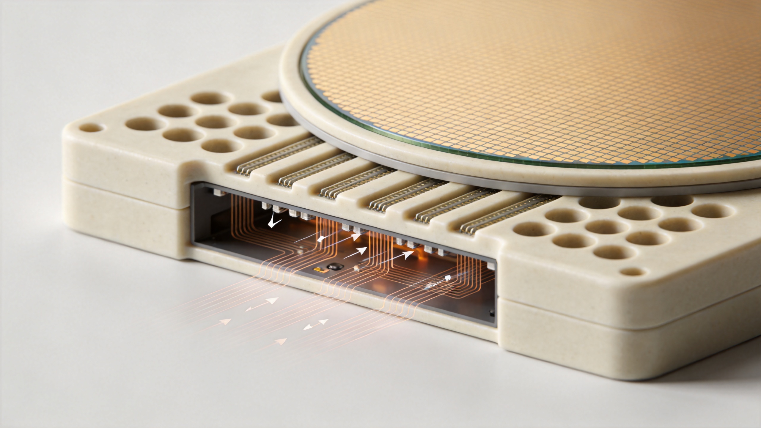
A typical ceramic vacuum chuck plate has a porous or patterned ceramic working surface supported by a base. The base connects to one or more vacuum ports, internal channels, or manifolds. When the system draws air from the gap beneath a wafer, the pressure below the wafer becomes lower than the pressure above it. Atmospheric pressure then presses the wafer toward the chuck surface.
That description also explains why a vacuum reading alone is not the full specification. The ceramic vacuum chuck plate must pass enough flow through the intended support area to establish holding force, while the distribution system must avoid concentrating that force at a few locations. Leakage at the wafer edge, a rough backside, an open unused zone, or a blocked passage can change the local pressure pattern. A process engineer should consider the whole path: pump capacity, tubing, valves, manifold geometry, vacuum zones, ceramic face, and the wafer itself.
Why porous ceramic changes the contact pattern
In a porous ceramic vacuum chuck, the contact face contains a network of fine, interconnected pores. Rather than depending only on a few drilled holes or broad grooves, a porous ceramic surface can spread suction across a larger area. This approach can be valuable when a thin or fragile wafer needs broadly distributed support. It does not remove the need for process validation; pore structure, surface finish, wafer backside condition, and vacuum setting still affect the actual contact condition.
A porous ceramic plate also needs a structure that balances airflow with mechanical stability. If the flow path is too restricted, evacuation can be slow or uneven. If the face geometry is poorly matched to the wafer or process, the wafer may not sit as intended. For that reason, a ceramic vacuum chuck plate should be evaluated as a designed assembly rather than as an isolated material disc.
Uniform support is different from high holding force
Higher suction is not automatically the right answer. The purpose of a ceramic vacuum chuck plate is to hold the wafer with sufficient stability while respecting the process limits. Thin wafers, delicate films, and patterned backsides may call for attention to local contact, pressure distribution, and release behavior. A flat, clean contact condition can be as important as the nominal vacuum level.
Consider a wafer that bridges small variations in the chuck face. A strong vacuum can pull it down, yet the resulting shape may not be appropriate for a measurement or exposure step. Conversely, a carefully designed ceramic substrate surface with suitable zones may provide a repeatable support condition without applying unnecessary local stress. The correct choice depends on wafer thickness, diameter, backside texture, edge exclusion, processing forces, and accuracy requirements.
What the ceramic surface contributes
The ceramic portion of a ceramic vacuum chuck plate provides the physical surface that meets the wafer. Its flatness, local texture, porosity or pattern, edge condition, and cleanliness all influence how the wafer seats. A ceramic surface may be selected for its dimensional stability and suitability for a precision-machined form, but the final performance remains application-specific.
During design review, separate material questions from component questions. Material questions include the appropriate ceramic family, pore characteristics, and compatibility with the intended cleaning approach. Component questions include overall diameter, thickness, vacuum-port locations, zone layout, sealing approach, mounting features, and the relationship between the ceramic substrate and its base. A durable answer requires both sets of information.
Vacuum zoning and edge leakage
Many applications benefit from dividing a ceramic vacuum chuck plate into independently controlled zones. A zone can be activated for the wafer area in use and isolated where there is no wafer coverage. This can reduce avoidable leakage and makes the fixture more adaptable across wafer sizes, provided the system design supports that flexibility.
Edge leakage is especially relevant when a wafer does not cover the full active area. Air entering around the edge can reduce the effective pressure difference across the wafer. Zoned control, correctly placed seals where appropriate, and an application-matched porous ceramic plate layout can help engineers manage the issue. The exact arrangement should be verified in the operating equipment rather than assumed from a general drawing.
Precision processing concerns beyond holding
A ceramic vacuum chuck plate supports more than retention. It can affect how consistently a wafer is presented to tools and sensors. For precision work, review flatness and parallelism targets, face finish, positional references, thermal conditions, cleaning procedure, particle-control practices, and the method used to verify wafer placement. If a process includes a change in temperature, rotation, acceleration, or a liquid environment, those conditions belong in the review as well.
It is also sensible to define how the wafer will release. The ceramic vacuum chuck plate should permit a controlled return to atmospheric pressure or another planned release sequence. Abrupt handling, residual vacuum in a zone, or a surface condition that has not been checked can complicate unloading even when holding appeared stable.
A practical RFQ checklist for a ceramic vacuum chuck plate
To turn a general inquiry into an engineering discussion, provide the following information:
- Wafer material, diameter, thickness range, and backside condition.
- Required active area, edge exclusion, and whether a porous ceramic vacuum chuck or a patterned face is preferred.
- Target flatness, parallelism, and surface-finish requirements for the assembled ceramic vacuum chuck plate.
- Vacuum-port connection, available vacuum level, zone requirements, and leakage conditions.
- Process environment: dry handling, cleaning chemicals, temperature changes, rotation, or applied process forces.
- Mounting envelope, datum features, drawings, inspection method, and acceptance criteria.
These details let a supplier discuss a porous ceramic face, base design, and assembly constraints without turning generic material claims into promises. They also help procurement and engineering align on what must be measured before production or replacement.
Conclusion
A ceramic vacuum chuck plate holds wafers by combining lower pressure beneath the workpiece with a controlled support surface. The vacuum source creates the pressure difference; the manifold and zones distribute it; and the ceramic face transfers that support to the wafer. In precision processing, the important result is not simply attachment. It is stable, repeatable, application-appropriate support. When specifying a ceramic vacuum chuck plate, review the wafer, the vacuum path, the surface, the mounting connection, and the inspection criteria as one system.

