 EN


How piezoelectric transducer converts electric signals and vibration energy
A piezoelectric transducer sits at the boundary between mechanics and electronics. Depending on how it is used, the same component can turn vibration, force, or pressure into an electrical signal, or turn an electrical drive signal into controlled motion. That two-way behavior is why a piezoelectric transducer appears in vibration sensing, ultrasonic equipment, positioning devices, alarms, and industrial monitoring assemblies.
From an application-engineering perspective, the useful question is not simply whether a piezoelectric transducer works. It is which conversion direction is needed, what frequency range is involved, and how the ceramic element will be mounted and connected. Those conditions determine whether the output is meaningful and repeatable.
The two energy-conversion directions
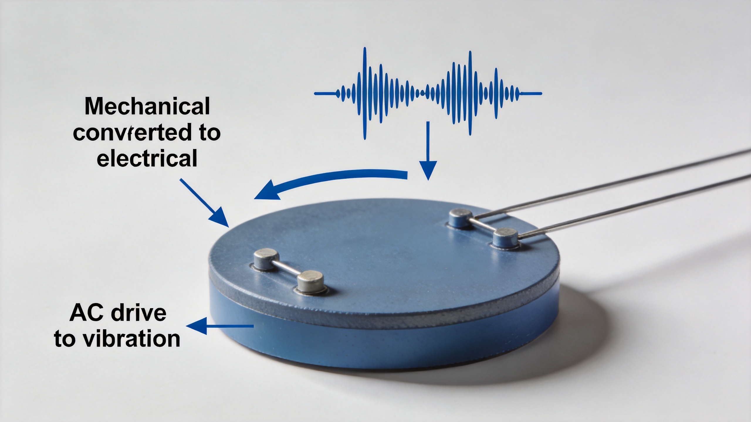
The direct piezoelectric effect is the sensing direction. When a mechanical load deforms a piezoelectric transducer, charge appears across its electrodes. A changing force, strain, or vibration can therefore become a voltage signal after suitable conditioning. In practice, this makes a piezoelectric transducer well suited to dynamic events rather than to a static load held for a long time.
The converse piezoelectric effect is the actuation direction. Apply an electric field across the element, and the piezoelectric transducer changes dimension by a small amount. With an alternating drive, that change repeats at the drive frequency and produces vibration. In an ultrasonic assembly, the mechanical design may use this repeated motion to couple energy into a horn, a fluid, a workpiece, or another load.
These effects are linked, but the surrounding system is different. A sensing circuit must preserve a small charge or voltage without loading it excessively. An actuator circuit must supply an appropriate electrical drive while accounting for capacitance, heating, resonance, and the mechanical load.
What is inside a piezoelectric transducer?
A typical piezoelectric transducer includes a polarized piezoelectric ceramic element, electrodes, leads or terminals, and a mechanical package. The ceramic is often arranged as a disc, ring, plate, stack, or bonded layer so that the applied field and intended motion align with the selected vibration mode. The electrodes distribute the electrical field; the enclosure and mounting path determine how force reaches the ceramic or leaves it.
Many designs use piezoelectric ceramics because they can be formed into practical shapes and integrated with electrodes. Material choice is not a stand-alone answer. A ceramic selected for a small sensing element may not suit a high-power ultrasonic assembly, and a material decision also has to consider drive level, temperature exposure, geometry, duty cycle, bonding method, and the required mode of vibration.
A ceramic substrate is related to electronic packaging, but it is not automatically the active piezoelectric layer. It may support conductors, add insulation, or help manage heat in a nearby assembly. Keeping those roles separate helps avoid a common specification mistake: treating every ceramic part as if it produces the transduction effect.
How an electrical signal becomes vibration
For actuation, a driver applies a voltage across the electrodes of the piezoelectric transducer. The electric field changes the shape of the polarized ceramic. A steady voltage produces a small static displacement, while an alternating voltage produces alternating expansion, contraction, bending, or shear motion. The mechanical output depends on the selected mode and on how freely the assembly can move.
Frequency matters because every piezoelectric transducer has mechanical resonances shaped by its dimensions, mass, stiffness, and attached load. Near a useful resonance, a relatively small material strain can produce a much larger system vibration. That is not a reason to assume a fixed output from a catalog description. Mounting torque, adhesive layers, backing materials, contact pressure, and the load medium can shift the operating behavior.
The electronics must also be considered as part of the conversion chain. A thick film circuit board can carry connections or supporting circuitry, but its layout and isolation requirements must suit the voltage, frequency, and noise sensitivity of the design. A thick film resistor may be used in a conditioning, damping, bias, or protection network when the circuit design calls for it. Neither component creates piezoelectric motion by itself; each supports the electrical environment around the active element.
How vibration becomes an electrical signal
In sensing mode, vibration or force stresses the piezoelectric transducer. The internal charge displacement appears at the electrodes and can be measured as charge or voltage. The signal level depends on the material, geometry, stress distribution, frequency content, cable capacitance, input impedance, and environmental noise. For this reason, a piezoelectric transducer is often paired with a charge amplifier or a high-input-impedance front end rather than connected directly to a general-purpose input.
A useful design check is to trace the whole path: source vibration, mounting contact path, piezoelectric transducer, cable, signal conditioner, and data-acquisition input. If any part of that path is poorly matched, a technically sound ceramic element can still yield an unstable or misleading measurement. In other words, a piezoelectric transducer should be specified as part of a system, not as an isolated part number.
Why resonance, loading, and mounting matter
It is tempting to focus only on the piezoelectric ceramics data sheet. More accurately, performance depends on the interaction between the ceramic and its surroundings. In a vibration sensor, loose mounting can reduce the fidelity of transmitted motion. In an ultrasonic actuator, an unsuitable mechanical load can change the resonance condition and alter energy transfer. Electrical loading can matter as well, particularly when the signal source is small or the drive is high frequency.
For a design that combines a piezoelectric transducer with a ceramic substrate or a thick film circuit board, clarify which parts carry structural load, which parts provide insulation, and which parts route or condition signals. That separation makes it easier to review clearances, electrode connections, thermal paths, and assembly stress before fabrication.
A practical specification checklist
Before requesting or evaluating a piezoelectric transducer, prepare the following information:
- Required direction: sensing, actuation, or both.
- Operating frequency range and whether operation is near resonance.
- Target force, vibration amplitude, pressure, or signal range.
- Element shape, outer dimensions, thickness, and electrode arrangement.
- Mounting method, preload, bonding material, and mechanical load.
- Drive voltage or signal-conditioning requirements, including cable length where relevant.
- Environmental limits such as temperature, humidity, and exposure to process media.
- Requirements for related parts, including a ceramic substrate, thick film resistor, or thick film circuit board where those items belong to the assembly.
For customized piezoelectric ceramics, a drawing and the operating conditions are usually more useful than a keyword alone. They allow the conversation to move from a general conversion principle to dimensions, frequency, electrical connections, and acceptance criteria that can actually be reviewed.
Key takeaway
A piezoelectric transducer converts energy through two complementary effects: mechanical stress can generate an electrical signal, and an electrical field can generate mechanical motion. The active ceramic is central, but the result depends on resonance, electrical loading, mounting, and the surrounding circuit. Define those conditions early, then assess the piezoelectric transducer together with the mechanical and electrical assembly it must serve.

